
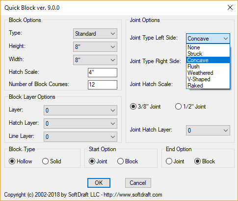
SoftDraft’s QuickBlock App easily creates CMU Block Wall Sections
🧱 CMU Wall Section Drafting Techniques
1. Use Standard CMU Dimensions
- Common CMU sizes: 8″x8″x16″, 6″x8″x16″, etc.
- Account for mortar joints (typically ⅜”) in overall wall thickness.
- Use blocks from CAD libraries like ARCAT or CADdetails for accurate geometry.
2. Layer Management
- Assign different components (blocks, mortar, rebar, insulation) to distinct layers.
- Use color coding and line weights to differentiate materials and improve readability.
3. Hatch Patterns for CMU
- Apply custom hatch patterns to represent CMU texture in section or elevation views.
- Create or modify hatch patterns to match block size and joint spacing.
4. Detailing Reinforcement
- Include vertical and horizontal rebar in wall cores.
- Use standard symbols and callouts for rebar sizes and spacing.
- Show bond beams and grout-filled cells where required.
5. Wall Style Customization (AutoCAD Architecture)
- Define wall styles with CMU components, including render materials and surface hatches.
- Use display overrides to control how CMU appears in plan, section, and elevation views.
6. Dimensioning and Annotation
- Clearly dimension block sizes, wall thickness, reinforcement spacing, and openings.
- Use consistent annotation styles for notes, tags, and callouts.
7. Use Blocks and Dynamic Components
- Create reusable block components for CMU units, lintels, bond beams, etc.
- Consider dynamic blocks for adjustable features like block size or orientation.
8. Reference Standards
- Follow CSI Section 042200 for CMU specifications.
- Include notes on materials, installation, and finishes per project standards.